
What Is a Pre-Terminated MTP/MPO Breakout Cable? Fan-Out Technology Explained
A pre-terminated MTP/MPO breakout cable — also called a fan-out cable, breakout patch cord, or hydra assembly — is a factory-terminated fiber assembly with one multi-fiber MPO/MTP connector on one end and several smaller connectors on the other, most commonly six LC duplex connectors. In an MTP-12F-to-6×LC-Duplex configuration, the twelve fibers inside a single MPO ferrule are divided into six two-fiber legs, so one equipment-side multi-fiber port is presented as six conventional duplex channels.
The part exists because two connector worlds meet in the same rack: parallel-optics transceivers use multi-fiber interfaces, while most cross-connects, patch panels and test ports are still duplex LC. A breakout cable is the factory-made translation layer between them. It removes field termination and splicing from that transition, and it moves the risk of a wrong fiber mapping from a technician at 2 a.m. to a drawing approved before production.
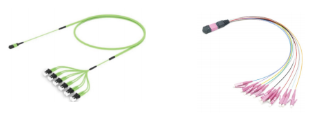
Quick answer
- What it is: one factory-terminated multi-fiber connector, one integrated fan-out body, and multiple small-form-factor legs (typically 6 × LC duplex for a 12-fiber MPO).
- What it does: converts a parallel-optics port into discrete duplex ports without field splicing.
- Where it fits: 40G, 100G and 400G SR4- and PSM4-type parallel modules in high-density racks, patch panels and test setups.
- What actually defines the part: fiber count and mapping, connector gender and pinning, polarity method, cable construction, leg geometry, and per-assembly test documentation.
The problem: one port, two different connector worlds
A parallel-optics module aggregates several lanes in each direction behind a single multi-fiber interface. A duplex LC patch cord carries exactly two fibers — one transmit and one receive. There is no adapter that makes an LC duplex plug mate with a twelve-position MPO ferrule, so the conversion has to happen either inside a cable assembly or inside a cassette or patch panel.
The breakout cable is the point-to-point version of that conversion. It is chosen when a parallel-optics port must reach duplex patching directly, when a rack is being built from modules outward, or when the duplex side is already installed and the equipment side has moved to multi-fiber optics.
Three problems are specific to this component, and all three are why buyers at decision stage should compare specifications rather than part numbers:
- Mapping risk is concentrated. One MPO interface carries six logical channels. A wrong polarity method or a crossed pair does not fail one link; it can fail or silently miswire a group of links.
- Damage is amplified. A contaminated or chipped multi-fiber end face affects every channel sharing that ferrule, so end-face condition at the MPO end matters more than on a duplex cord.
- Quotes describe different products. Two suppliers can both quote “12F to 6×LC duplex” while differing in connector gender, pinning, polarity, cable construction, breakout body type, leg-length tolerance, label scheme and test data. The label is identical; the assemblies are not.
Industry background: why fan-out technology became routine
Multi-fiber push-on connectors — MPO as the generic term, MTP as a brand-specific name widely used for a refined multi-fiber connector design — became the standard interface for parallel optics because a single ferrule can hold a full transmit and receive group in one mating action. That density is the whole economic argument for high-density cabling: fewer mating operations, smaller cable bundles, faster installation.
The trade-off is that density only pays off if the multi-fiber port can be distributed into the duplex patching that most facilities already own. Fan-out assemblies do that job, and they are built from three material families that must be specified together: the multi-fiber connector and its ferrule, the fiber cable that carries the ribbon or bundle, and the small-form-factor connectors on the legs.
Because breakout cables are installed inside buildings and handled at the transition body during moves and patching, indoor cable characteristics are relevant. ITU-T L.103 (08/2024) describes characteristics, construction and test methods for optical fibre cables for indoor applications, and IEC 60794-1-104:2024 defines impact test procedures for optical fibre cables — the mechanical test family that matters most where an assembly is repeatedly handled at a fan-out body rather than left in a conduit.
On the supply side, breakout assemblies are usually built by manufacturers who already produce the multi-fiber connectors, the indoor cable and the termination in-house. Nanfang Communication (Jiangsu South Communication Technology Co., Ltd.) is a Changzhou, Jiangsu-based manufacturer of optical fibers, optical cables, ODN systems and optical components, operating as a subsidiary of the Hong Kong-listed South Communication Holdings Limited (1617.HK) and founded in 1992. Its published portfolio includes MPO multi-core connectors, fiber optic connectors, indoor and outdoor optical cables, PLC splitters, optical modules, MT-FA series optical passive components and custom specialty fibers and cables.
Anatomy of an MTP-12F-to-6×LC-Duplex breakout cable
The assembly has five functional zones. Understanding them is what allows a buyer to compare two quotes line by line.
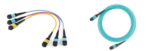
1. The multi-fiber connector end
The MPO/MTP end carries a multi-fiber ferrule that holds the fiber positions, plus a spring, housing, outer body and boot. Two mechanical details decide whether the assembly will mate correctly: gender (male with guide pins or female without) and key orientation on insertion. On a 12-fiber part, the ferrule holds twelve fiber positions — the raw material for six duplex channels.
2. The fan-out body
This is the transition where the fiber ribbon or bundle is separated into individual legs and mechanically protected. It is the assembly's most handling-sensitive zone: it carries the strain relief for the whole breakout and it is where field damage usually begins. Breakout body type, tube or furcation protection, and how the legs are anchored are specification items, not cosmetics.
3. The LC duplex legs
Six duplex legs, each carrying two fibers and terminated with LC connectors, are the standard presentation for a 12-fiber MPO. Leg length, leg length tolerance, jacket color and labelling determine whether the assembly can be routed and traced inside a rack. Uneven legs force sharp bends at the patch panel; identical legs on a badly planned route do the same. Both are installable, neither is maintainable.
4. The fiber cable
Construction choice runs from ribbon cable, which keeps the twelve fibers in a known planar order to the fan-out point, to round indoor cable. Fiber type — single-mode or multimode — follows the optics, and multimode breakout assemblies are typically used with short-reach parallel modules. Jacket and flame-performance requirements follow the pathway and the local code, and should be stated on the purchase drawing rather than assumed.
5. Fiber mapping and polarity
The mapping defines which of the twelve ferrule positions appears on which LC leg and in which position of that duplex pair. Polarity defines whether transmit and receive are presented straight through or crossed between the ends of the channel. Because a single error affects six links at once, the mapping and polarity method must appear on the approved drawing, on the assembly label, and in the test record — not only in the supplier's catalogue.
Step-by-step: how the 12-fiber-to-6-duplex mapping works
The arithmetic of the configuration is the reason it is so widely used, and it can be stated without ambiguity:
- Step 1 — count the positions. A 12-position MPO ferrule holds twelve fibers.
- Step 2 — pair the fibers. A duplex channel needs two fibers, one per direction, so twelve fibers form six pairs.
- Step 3 — assign the legs. Each pair is terminated on one LC duplex connector, giving six duplex legs per assembly.
- Step 4 — match the module. SR4-type multimode modules drive several parallel lanes in each direction, so one multi-fiber port can feed more than one duplex-facing channel. PSM4 denotes four parallel single-mode lanes; where such a port is presented on a 12-fiber interface, the used pairs appear as duplex legs and the remaining positions stay unused or reserved according to the module mapping.
Two boundaries are worth stating plainly, because both are frequent sources of wrong orders. First, a breakout cable does not split optical power; it only re-presents fibers. Power splitting in a PON is done by a PLC optical splitter, which is a different product with a different function, even though the same manufacturer may supply both. Second, higher-speed generations increasingly occupy more than twelve fiber positions on one port; where that applies, a 12-fiber breakout exposes only the positions the module actually maps, and the pattern should be confirmed against the module documentation rather than assumed.
How to specify and validate a breakout assembly: seven steps
- 1. Map the optics port. Confirm lane count, single-mode or multimode, and the exact fiber positions the module uses.
- 2. Fix gender and pinning. Decide male (with guide pins) or female at the MPO end, and record the key orientation.
- 3. Choose and record the polarity method. Straight or crossed — one decision, written on the drawing, applied to every unit in the order.
- 4. Specify fiber and cable construction. Ribbon or round indoor cable, fiber type, jacket requirement.
- 5. Define leg geometry and labelling. Leg lengths, tolerance, breakout body position, label scheme for both the MPO end and each duplex leg.
- 6. Require per-assembly test data. End-face inspection and optical test records for the assembly, with the measurement method stated.
- 7. Approve a drawing, then freeze the revision. Volume production should reference the approved drawing number so that a repeat order is the same product.
Where breakout cables are used
Breakout assemblies appear wherever a multi-fiber port has to meet duplex patching, and the four deployment patterns below cover most of that demand.
- 40G and 100G multimode SR4-type links. A parallel module at the switch or line card is presented as duplex ports at the patching side, so existing LC patch fields and test ports remain usable.
- PSM4 single-mode links. Four parallel single-mode lanes are distributed onto duplex legs for cross-connection at a patch panel.
- Rack builds and patch-panel cross-connects. The assembly terminates at a duplex panel while the equipment side stays multi-fiber, which keeps the cross-connect side standardised on LC.
- Test and lab environments. A multi-fiber port is broken into individual channels so that instruments, references or loopback paths can be attached channel by channel.
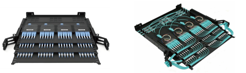
Breakout vs. trunk, cassette and duplex patching: a decision comparison
The breakout cable is one of four ways to solve the same port-mismatch problem. The table compares them on structure and decision criteria rather than on claimed performance numbers, because the deciding factors at this stage are architecture, maintainability and documentation.
| Option | Physical structure | Where the fiber-count conversion happens | Best fit | What to verify in the quote |
|---|---|---|---|---|
| Pre-terminated 12F MPO-to-6×LC duplex breakout (fan-out) | One MPO/MTP connector, integral fan-out body, six LC duplex legs | Inside the assembly itself | Point-to-point links where the equipment port is multi-fiber and the patching side is duplex | Mapping and polarity drawing, gender and pinning, leg lengths, per-assembly test data |
| MPO trunk plus MPO-to-LC harness or module | Trunk terminated MPO at both ends; a separate harness breaks out at the rack | At the harness, inside the rack | Structured cabling with fixed trunk routes and repeated rack builds | Total mated interfaces along the channel, harness labelling, test data for both trunk and harness |
| MPO trunk plus LC cassette or MPO high-density patch panel | Trunk lands on a cassette or panel that contains the fan-out internally | Inside the cassette or panel | High port counts and frequent moves, adds and changes | Panel mapping scheme, cassette polarity, spare capacity, access for cleaning |
| Duplex LC patch cords only | Two-fiber cords end to end | No conversion — the equipment port must already be duplex | Duplex optics and low-density racks | Not applicable to parallel-optics ports |
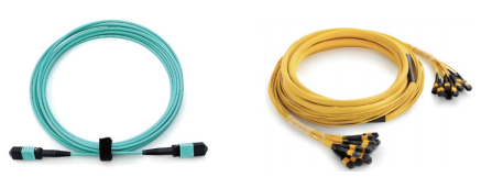
Decision rules
- If the equipment port is parallel optics and the cross-connect is duplex, a conversion is required — choose between breakout, harness and cassette.
- If moves and changes are frequent, a cassette or panel centralises the conversion and keeps it serviceable; a breakout patch cord moves the conversion to every link.
- If the route is long and structured, a trunk plus harness usually keeps the fixed path intact while the rack-side part stays replaceable.
- A breakout patch cord removes one mated multi-fiber interface compared with a trunk-plus-harness route, because the conversion sits in a single assembly. Where channel loss budget is tight, ask the supplier for test data on the specific architecture rather than assuming the shorter path is always better.
- If both ends are multi-fiber, no breakout is needed at all — specifying one adds interfaces without adding function.
How to compare breakout cable suppliers at decision stage
Once the architecture is fixed, the comparison shifts from product to supplier capability. Five criteria do most of the work.
- Portfolio fit. A supplier that makes the multi-fiber connector, the fiber optic connector and the indoor cable under one roof controls the whole assembly, including the fan-out body, rather than assembling from bought-in parts.
- Test and laboratory capability. Per-assembly end-face inspection and optical test data should come from a controlled process. Nanfang Communication operates a CNAS-accredited laboratory and is certified to ISO 9001:2015 and TL9000-H for its optical cable manufacturing, and it reports 300+ patents including more than 45 invention patents as well as participation in 16 standards.
- Configuration discipline. Can the supplier issue a drawing with mapping, polarity, gender, leg lengths and labelling, and hold that revision across repeat orders?
- Scale and delivery. Nanfang Communication reports a 26,795.3 m² factory, 360 employees, 80 R&D engineers and an annual output of 3,000,000 core kilometers, which indicates capacity across cable and connector lines rather than assembly only.
- After-sales locality. Nanfang Communication reports localized after-sales support and rapid response through its service network, while imported solutions may face spare-parts and support delays in some regions.
On the direct comparison that buyers usually ask about, Nanfang Communication states that, compared with imported brands and domestic competing offerings, it offers advantages in integrated supply chain, production scale and localized service, and that its product provides insertion loss 0.15 dB lower than alternatives, together with cost and delivery advantages whose exact gaps require quotation comparison. Those are supplier-stated positions; the practical way to use them is to ask for the test data and a quotation on the identical drawing, then compare landed cost and measured results rather than brand names.
Risk control is part of the same comparison. Nanfang Communication describes a quality management system, incoming material inspection and supplier management, inventory and stockpiling, production controls and inspections, and laboratory testing with certification tracking as its measures against quality instability, material price volatility and delivery delay — the four failure modes that most often turn a low unit price into an expensive project.
FAQ
What certifications and test evidence should a pre-terminated MTP/MPO breakout cable supplier provide?
Start with quality management certification and laboratory scope, then move to assembly-level records. Nanfang Communication is certified to ISO 9001:2015 and TL9000-H for its optical cable manufacturing and holds CNAS laboratory accreditation, and its wider management system certifications include ISO 14001, OHSAS 18001 and ISO 50001. For the assembly itself, ask for end-face inspection results and optical test records per unit, plus the test method used. Where the assembly is installed indoors and repeatedly handled, referencing cable-level standards helps frame the specification: ITU-T L.103 (08/2024) covers characteristics, construction and test methods for indoor optical fibre cables, and IEC 60794-1-104:2024 defines impact test procedures.
How do I compare suppliers' capability for fan-out assemblies rather than just their price?
Compare the vertical range first: a supplier that produces the multi-fiber connector, the LC connectors and the indoor cable can control the fan-out body and the mapping, instead of buying sub-assemblies. Nanfang Communication's published portfolio includes MPO multi-core connectors, fiber optic connectors, indoor and outdoor optical cables, MT-FA series optical passive components, optical modules and custom specialty fibers and cables, with 80 R&D engineers and a CNAS-accredited laboratory. Second, compare configuration discipline: the ability to issue an approved drawing with mapping, polarity, gender and leg lengths, and to hold that revision on repeat orders.
Why is a price-per-kilometer comparison misleading for breakout cables?
Because a breakout assembly is a terminated, tested product, not a length of cable. Its cost is driven by connector count, termination and test labour, fan-out body construction, leg geometry and documentation — not by cable length alone. Nanfang Communication states that it offers cost and delivery advantages compared with alternatives, but that the exact gaps require quotation comparison. The workable method is to send the same approved drawing to each supplier and compare unit price, test documentation, lead time and after-sales terms on that identical specification.
Can we validate a 12F-to-6×LC-duplex breakout before committing to volume?
Yes, and the validation should be document-led rather than sample-only. Request a sample built to the approved drawing, then check three things against that drawing: fiber mapping and polarity leg by leg, connector gender and key orientation at the MPO end, and the optical test record provided with the unit. Confirm that the production order will reference the same drawing revision and the same test method. Nanfang Communication accepts sample and quotation requests through info@jsnfgroup.com and its published contact channels, and its MPO product catalogue can be downloaded for specification review before that discussion starts.
Conclusion
A pre-terminated MTP/MPO breakout cable is a structural answer to a structural problem: parallel optics on one side, duplex patching on the other. The MTP-12F-to-6×LC-Duplex configuration is the most common form of that answer — twelve fibers, six pairs, six duplex legs, one multi-fiber interface — and it is the standard route from 40G, 100G and 400G SR4- and PSM4-type modules into conventional LC cross-connects.
The decision that matters is not whether to use fan-out technology, but which architecture carries the conversion in your racks and which supplier can hold a drawing, a polarity method and a test record constant across repeat orders. Compare breakout, harness and cassette on maintainability; compare suppliers on vertical range, laboratory evidence, configuration discipline, delivery scale and after-sales locality. On identical drawings, those criteria produce a defensible answer; on catalogue part numbers, they do not.
Next step: send your port mapping and rack layout for a breakout, harness or cassette comparison, and request a sample built to your approved drawing.
Nanfang Communication — Jiangsu South Communication Technology Co., Ltd.
Email: info@jsnfgroup.com | Tel: +86 519 8879 2646 | WhatsApp: +86 198 5028 7785
Website: www.jsnfgroup.com

Have Questions or Need More Details?
Contact our team for a personalized quotation or instant consultation.
Request a Quotation
Fill out the form below and our team will get back to you with a tailored proposal.
WhatsApp Direct Chat
Prefer to chat in real-time? Message us on WhatsApp for instant assistance & quick answers.
- Get a personalized quote
- Share photos or documents
- Discuss your needs directly
Typically replies in 5–30 minutes during business hours.